Trackdyne Documentation
Main ❯ Navigation & tracking systems ❯ VigilArc USBL: User’s manual
ℹ Recommendations for printing / saving as PDF
- Press Ctrl+P (macOS: Cmd+P)
- Select "Save as PDF" (Microsoft Print to PDF) as the printer
- In "Pages", enter a range that excludes the first and the last page
- Disable headers and footers (title, URL, page numbers)
- In Chrome/Edge: More settings → "Margins" → None | in Firefox: "Margins & Header/Footer" → None
- Click Print and choose where to save the PDF
 |
 |
|---|---|
| trackdyne.com support@trackdyne.com |
VigilArc USBL - underwater acoustic navigation system User’s manual |
VigilArc USBL
User’s manual
Contents
- 1.1. Purpose
- 1.2. Features
- 1.3. System composition
- 1.4. Versions
- 2.0. Before operation
- 2.1. Preparation for operation and equipment check
- 2.2. Working with the system
- 2.2.1. Interacting with the system
- 2.3. After operation
- 3.1. Terms of replacement and free warranty service
- 3.2. Limitation of the manufacturer’s liability
1. Introduction
1.1. Purpose
The VigilArc underwater acoustic navigation system is designed to determine, in real time, the location of underwater objects equipped with VigilArc Tag responder-beacons.
The responder-beacons (hereinafter, beacons) can be installed on:
- remotely operated underwater vehicles (ROVs)
- human-occupied vehicles (HOVs)
- autonomous unmanned underwater vehicles (AUVs)
- recreational and technical divers (when the standalone version of the beacon is used).
The system makes it possible to determine:
- the relative location of underwater objects (azimuth angle, range, depth)
- the absolute location of underwater objects (latitude, longitude, depth) when external sources of navigation data (a GNSS receiver and a compass) are used.
1.2. Features
The VigilArc navigation system is an ultra-short baseline (USBL) navigation system whose principle of operation is based on the use of a phased antenna array to determine the horizontal angle of arrival of the signal and on determining the distance to the beacon by the “request-response” method. The VigilArc system uses modern digital wideband, noise-resistant underwater acoustic communication technology, and its signal is specifically designed for difficult hydrological conditions, including those typical of shallow bodies of water.
1.3. System composition
The system includes:
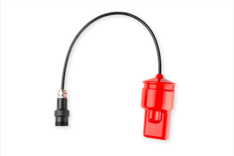
- Direction-finding antenna VigilArc Array
- Cable with an integrated RS-422 interface converter
- Responder-beacon VigilArc Tag
- Power supply and switching unit VigilArc Deck
 |
|---|
| Direction-finding antenna VigilArc Array |
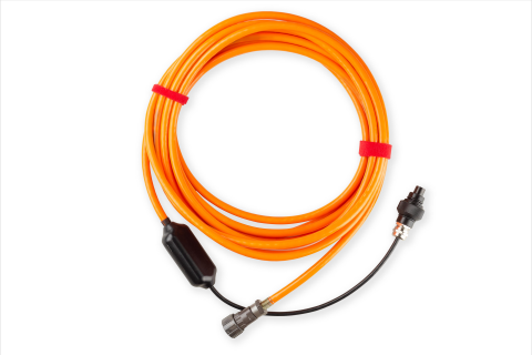 |
| UART-RS422 cable with an integrated interface converter |
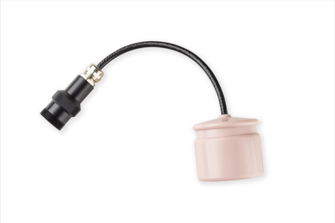 |
| Responder-beacon VigilArc Tag (integrated version) |
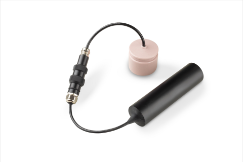 |
| Responder-beacon VigilArc Tag with a battery pack (standalone version) |
| Power supply and switching unit VigilArc Deck |
We are constantly working to improve our products, so the appearance, color, and type of the connectors, cables and chargers used may differ slightly.
1.4. Versions
The system is available in different versions for different depth ranges. When this document refers to the base version of a device, for example VigilArc Array, it should be understood as applying to all versions of the device, unless additional clarifications are given.
CAUTION! Devices of different versions are not compatible with each other, and using them together in one system will inevitably result in incorrect navigation data.
1.4.1. Standard version
In the standard version, the system can operate at depths of up to 300 m. The responder-beacon can be powered either from the carrier or from a standalone source.
| Device | Technical specification |
|---|---|
| Direction-finding antenna VigilArc Array |  |
| Responder-beacon VigilArc Tag |  |
1.4.2. Version 35
In this version, the system can work with responder-beacons located at depths of up to 350 m. The built-in pressure sensors in the responder-beacons have a protective metal diaphragm. The responder-beacon can be powered either from the carrier or from a standalone source.
| Device | Technical specification |
|---|---|
| Direction-finding antenna VigilArc Array 35 |  |
| Responder-beacon VigilArc Tag 35 |  |
2. Working with the VigilArc system
2.0. Before operation
Before heading out to the water, make sure that all equipment is fully charged and, if necessary, charge all devices.
Pay particular attention to the power supply and switching units and the responder-beacons: since these devices have built-in power sources based on LiFePO4, their discharge curve is very flat and it is difficult to determine the state of charge of the built-in source. Therefore, it is recommended to charge all devices before use, no earlier than 1–2 days in advance.
We use batteries based on LiFePO4 because they are the most durable and withstand the greatest number of charge-discharge cycles compared to Li-ion and Li-Po batteries, and can also operate at low temperatures.
2.1. Preparation for operation and equipment check
2.1.1. Positioning and setting up the direction-finding antenna
Mount the antenna with the supplied bracket. The cutout in the upper part of the bracket marks the zero direction of the antenna.
CAUTION!!!
UNLIKE THE PREVIOUS VERSION OF THE SYSTEM, THE POSITION OF THE ZERO DIRECTION OF THE ANTENNA HAS BEEN CHANGED!
The zero direction of the antenna coincides with the molding seam on the side where the antenna array is closer to the surface of the cylinder (see the figure below). The Z axis points down; the azimuth angle is measured clockwise from the zero direction when looking at the antenna from the cable side.
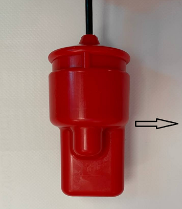 |
|---|
| Zero direction of the antenna |
| The horizontal angle is measured clockwise from the zero direction of the antenna, the vertical axis points down |
Because the antenna determines the horizontal angle of arrival of the signal relative to its zero direction, observe the following requirements when mounting it:
- The antenna must be placed on a deployment pole that holds it in a stable position no closer than 2 m to the water surface and no higher than 1.5 from the lowest point of the vessel’s keel
- The antenna must be secured with a clamp in such a way that its position does not change during operation (the antenna must not rotate inside the clamp)
- The antenna must not be squeezed too tightly by the mount
- The mount and its parts must not protrude below the mounting groove and thereby cover the working surfaces of the antenna
- The mount and its parts must not block the pressure sensor opening
- The thin cable coming out of the antenna must not be bent with a radius of less than 50 mm, the thick cable - with a radius of less than 100 mm.
It is not recommended to install the antenna near large objects: quay walls, piers, breakwaters, large vessels, massive supports and other water infrastructure objects.
The antenna is connected to the power supply and switching unit using an extension cable with an integrated interface converter. The cable has two connectors: one topside - for connecting to the power supply and switching unit, the other underwater - for connecting the antenna.
Before submerging the antenna, make sure that:
- there is no moisture, traces of corrosion or contamination in either part of the antenna’s underwater connector
- the seals on both parts of the underwater connector are intact
- there is a sufficient amount of thick silicone grease on the seals of the underwater connector
- the connector is mated and the locking ring is screwed on tightly by hand
CAUTION!
Water ingress into any connector is absolutely unacceptable and will result in damage not covered by the warranty!
The extension cable must not have large slack along its submerged length. It is recommended to secure the cable to the pole with rope or nylon cable ties.
CAUTION!
Before connecting the antenna to the power supply and switching unit via the extension cable, make sure that the power supply and switching unit is switched off!
The following sequence of actions is recommended when installing the antenna:
- check the underwater connector of the antenna
- connect the antenna to the extension cable by mating and tightening the underwater connector
- install the antenna in the clamp
- secure the cable to the pole with nylon cable ties or pieces of rope at points spaced no more than 500 mm apart
- make sure that the power supply and switching unit is switched off
- connect the topside connector of the extension cable to the power supply and switching unit
- connect the power supply and switching unit to the PC using a USB-B cable
For the version of the power supply and switching unit with two channels (for connecting an external GNSS compass), additional steps are required:
- connect the GNSS compass to the supplied cable
- connect the GNSS compass cable to the power supply and switching unit
Switch on the power supply and switching unit only after the host PC is ready to communicate with the system.
To find out the names of the connectors on the panel of the power supply and switching unit, refer to the user’s manual of the VigilArc Deck power supply and switching unit.
2.1.2. Mounting the responder-beacon on the carrier
The responder-beacon must be fastened only by its mounting groove, using a soft clamp, so as to avoid any uneven loading of the beacon housing, excessive squeezing, and shading/shielding of the beacon housing. The figure below shows the basic requirements for mounting the acoustic part of the responder-beacon on the carrier:
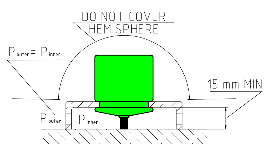 |
|---|
| Requirements for mounting the acoustic part of the responder-beacon on the carrier |
| Shielding of the spatial hemisphere or of the parts of the transducer located above the mounting groove is not allowed; the pressure in the area under the mount must be balanced with the external pressure |
The responder-beacon should not be positioned near thruster or propeller wash or directly in its path. The system requires a direct line of sight (through the water column) between the direction-finding antenna and the responder-beacon, so the beacon must be installed at the highest point of the carrier.
For a responder-beacon in the standalone version: A responder-beacon in the standalone version switches on automatically when it enters the water. Keep in mind that, immediately after switching on, the responder-beacon determines the atmospheric pressure for 5 seconds for a more accurate depth measurement. Therefore, it is recommended to first immerse the battery pack in the water and wait 5 seconds before immersing the responder-beacon itself.
CAUTION! If the battery pack is deeply discharged, a charger must be connected to it as soon as possible. Otherwise, this may result in damage to the battery pack.
For a responder-beacon in the integrated version: A responder-beacon in the integrated version switches on when power is supplied from an external system. After switching on, the responder-beacon determines the atmospheric pressure for 5 seconds for a more accurate depth measurement. If the current value of the external pressure is more than 1200 mbar, the beacon assumes that it was switched on while submerged, and the atmospheric pressure calibration does not take place.
The operability of the responder-beacon is easy to check by switching it on: 2 seconds after power is applied, a navigation signal is emitted once.
In the version with the standard connector, the water-activation contacts are located on both parts of the connector: on the beacon and on the mating part. Thus, when the standard battery pack is used, the device switches on when the mated connector is immersed in water.
2.1.3. Antenna and compass alignment
The zero direction of the direction-finding antenna and the zero direction of the compass may not coincide, for example because of inaccurate installation of the antenna in its bracket. This introduces a systematic error in the azimuth to the responder-beacon.
Measure the angular offset between these directions and the positional offset between the antenna and the GNSS receiver. Account for both offsets when converting relative measurements to geographic coordinates. Check the alignment whenever the antenna is reinstalled or the bracket is subjected to a strong mechanical impact.
2.2. Working with the system
For integration with a host system, use the VigilArc communication protocol specification. It describes device configuration, requests to responder-beacons and measurement output.
The measurement setup must account for the beacon addresses, water salinity and maximum operating range. Conversion to geographic coordinates also requires the antenna position, heading and installation offsets.
2.2.1. Interacting with the system
At this stage it is assumed that:
- The antenna’s underwater connector has been checked and mated (the extension cable is connected to the direction-finding antenna)
- The antenna is properly secured to the pole, and the extension cable has no slack
- The topside connector of the extension cable is connected to the power supply and switching unit, and the unit itself is switched off
- The power supply and switching unit is connected to the PC with a USB-B cable
- If a two-channel power supply and switching unit is used:
- The external GNSS compass is connected to the power supply and switching unit
- The offset of the direction-finding antenna relative to the position reference point (the position of the GNSS receiver) has been measured
- The angle between the zero direction of the compass and that of the direction-finding antenna has been measured
- The second channel of the power supply and switching unit is connected to the PC with a USB-B cable
- All responder-beacons that are to be used have different addresses
- If responder-beacons in the standalone version are used, the connectors joining them to the battery packs have been checked and are tightly mated, and the battery packs are fully charged
- If responder-beacons in the integrated version are used, the cable connections to the carrier have been checked for watertightness (according to the connection type)
It is recommended to switch the beacons on at the surface: in this case, atmospheric pressure calibration takes place during the first five seconds after power is applied, which allows depth to be measured with greater absolute accuracy.
Since standalone beacons switch on when the battery pack is immersed in water, it is recommended to immerse the battery pack in the water first, and the responder-beacon itself only after five seconds have passed.
Beacons in the integrated version should preferably be switched on before immersion, if this is possible under the current conditions.
Establish communication with the direction-finding antenna according to the communication protocol specification.
Keep in mind the factors that reduce the efficiency of the system, in particular:
- insufficient depth of the direction-finding antenna
- location in the immediate vicinity of massive, weakly absorbing infrastructure objects and vessels
- absence of a direct line of sight through the water column between the direction-finding antenna and the responder-beacons
- high noise level (both electromagnetic interference, for example in the vessel’s power supply network, and acoustic noise - the running engine of the vessel or carrier, surf, other underwater acoustic systems, for example - sonars, etc.)
- shallow water depth, and small bodies of water in general, create difficult hydrological conditions for the operation of underwater acoustic navigation and communication systems
- shielding of the direction-finding antenna and of the transducers of the responder-beacons
- exposure of the antennas to turbulent thruster/propeller wash and/or to the wake
- water density stratification (thermocline, etc.)
2.3. After operation
- Switch off the power supply and switching unit
- Disconnect all connectors on the panel of the power supply and switching unit
- Close all connectors that have transport plugs
- If there is any contamination, or after work in salt water, rinse all submersible parts of the equipment in fresh water
- Remove the direction-finding antenna from the pole
- For long-term storage (more than a week) or for transportation, unmate the underwater connector
- Before packing the equipment in its transport case, remove all moisture by natural drying, out of direct sunlight
- For responder-beacons in the integrated version, if they cannot be removed from the carrier, rinsing in fresh water and removal of any contamination is mandatory
3. Obligations and disclaimer
3.1. Terms of replacement and free warranty service
The manufacturer’s warranty covers only factory defects that become apparent during operation of the device in accordance with this manual during the warranty period (2 years from the date of purchase).
The manufacturer guarantees free repair or replacement of faulty equipment from the delivery set that has failed due to a factory defect.
Grounds for refusing free warranty service, free repair and replacement include:
- any mechanical damage to the equipment from the delivery set, including damage to the insulation of wires and cables;
- any damage caused by exposure to moisture and contamination as a result of improper operation of the equipment from the delivery set;
- any electrical damage caused by the use of accessories not included in the delivery set (chargers); accessories supplied by the manufacturer or its representative to replace faulty or lost ones are not considered to be outside the delivery set;
- any signs of unauthorized repair and/or opening of the equipment from the delivery set.
3.2. Limitation of the manufacturer’s liability
ANY OF THE PARTS OF THE DELIVERY SET, INDIVIDUALLY AND AS PART OF THE SYSTEM, HEREINAFTER REFERRED TO AS THE “SUPPLIED EQUIPMENT”:
- WAS NOT DESIGNED AS RESCUE EQUIPMENT
- WAS NOT TESTED AS RESCUE EQUIPMENT
- IS NOT RESCUE EQUIPMENT
- THE MANUFACTURER DECLARES THAT THE SUPPLIED EQUIPMENT IS SAFE WHEN OPERATED IN ACCORDANCE WITH THESE INSTRUCTIONS, AND THE MANUFACTURER IS NOT RESPONSIBLE FOR ANY CONSEQUENCES OF THE USE OF THE SUPPLIED EQUIPMENT
THE MANUFACTURER GUARANTEES THAT THE VigilArc UNDERWATER ACOUSTIC SYSTEM (HEREINAFTER - THE SYSTEM):
- IS INTENDED ONLY FOR USE WITH RESPONDER-BEACONS DESIGNED TO OPERATE TOGETHER WITH THE SYSTEM
- BY DESIGN CANNOT BE USED FOR TRACKING OBJECTS THAT ARE NOT EQUIPPED WITH RESPONDER-BEACONS DESIGNED TO OPERATE TOGETHER WITH THE SYSTEM
- DOES NOT CONTAIN MEANS OF RADIO COMMUNICATION, OR OF RECORDING AND LONG-TERM STORAGE OF AUDIO SIGNALS
THE ABOVE LIMITATIONS CANNOT BE LIFTED BY ANY MANIPULATION OF THE SETTINGS AND/OR CONTROLS OF THE SYSTEM DEVICES AND/OR OF THE SOFTWARE INTENDED FOR USE WITH THE SYSTEM